The TORBAL ODYSSEY series offers complete configurability and manageability of your force testing applications. The ODYSSEY is ideal for use in R&D, laboratory, or production settings where force measurements must be performed under strictly controlled conditions and variables. Optimized and fully compatible with all TORBAL force gauges. The series includes the FTV Vertical and FTH Horizontal models. The FTV is available in 11.8in and 19.6in travel range, with a maximum load capacity of 100lbF. The FTH has 11.8in of travel and a maximum load capacity of 100lbF. Both models are equipped with a built-in wireless data transmitter which allows for a cable-free connection of the force gauge to the test stand, thereby eliminating the need for cables or wires. The ODYSSEY is easily programmed through its five application modes: Peak, Cycle, Step, Advanced, and Manual. Each mode includes all essential configuration parameters to assure tests are performed with utmost precision and accuracy. Precise control of speed, distance, direction, and peak detection makes the ODYSSEY ideal for virtually any tension or compression testing application.
Test Stand Orientation
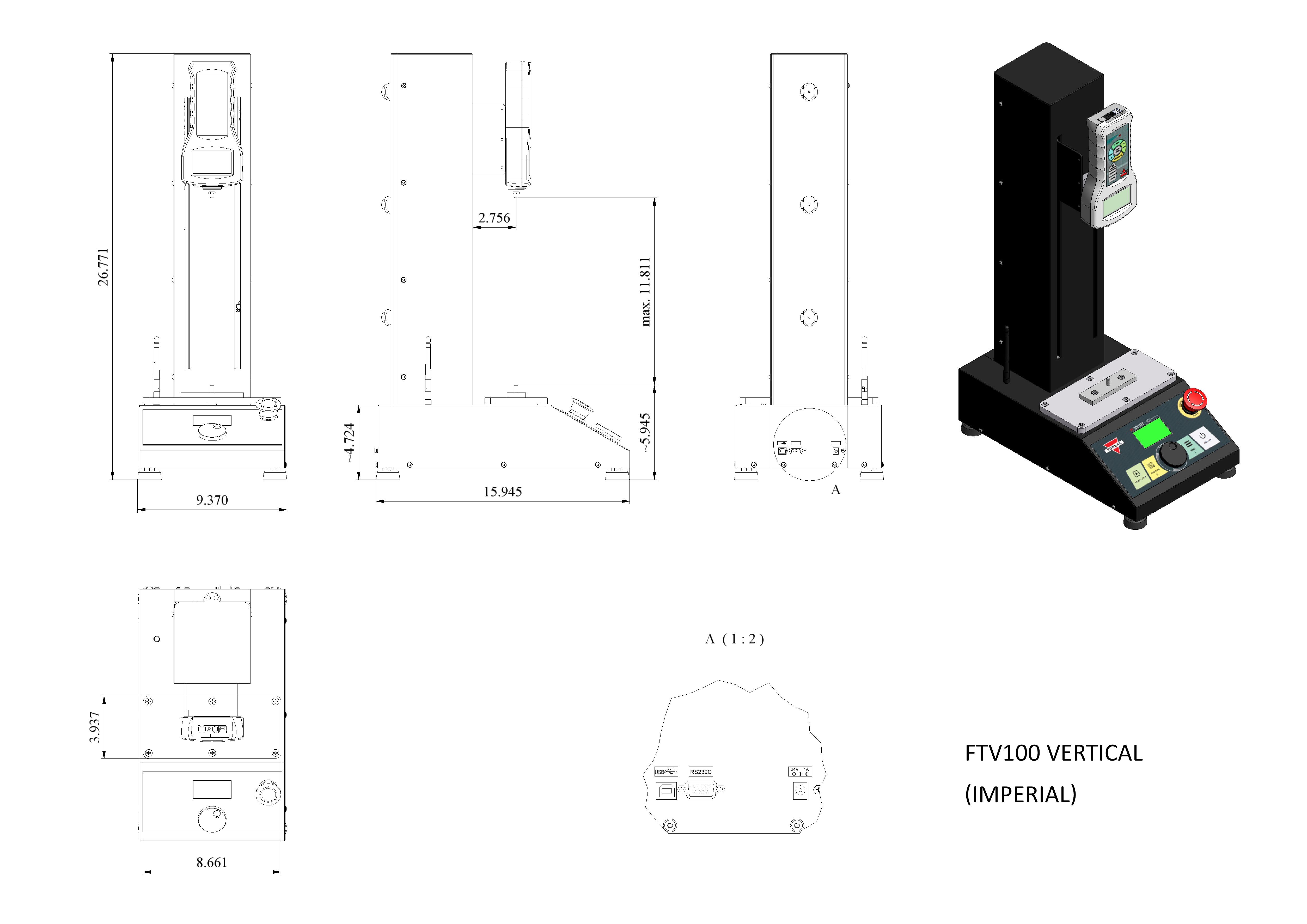
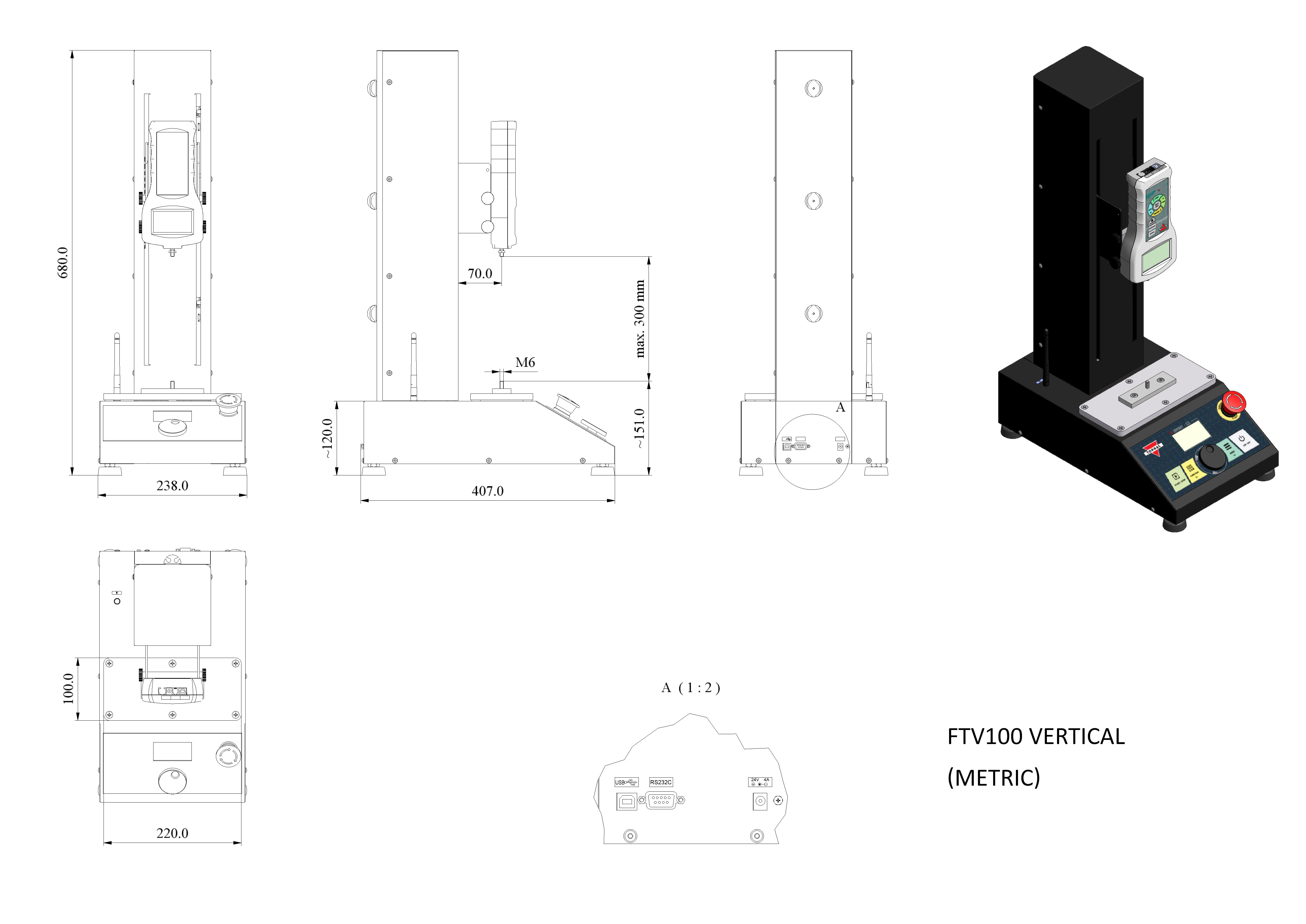
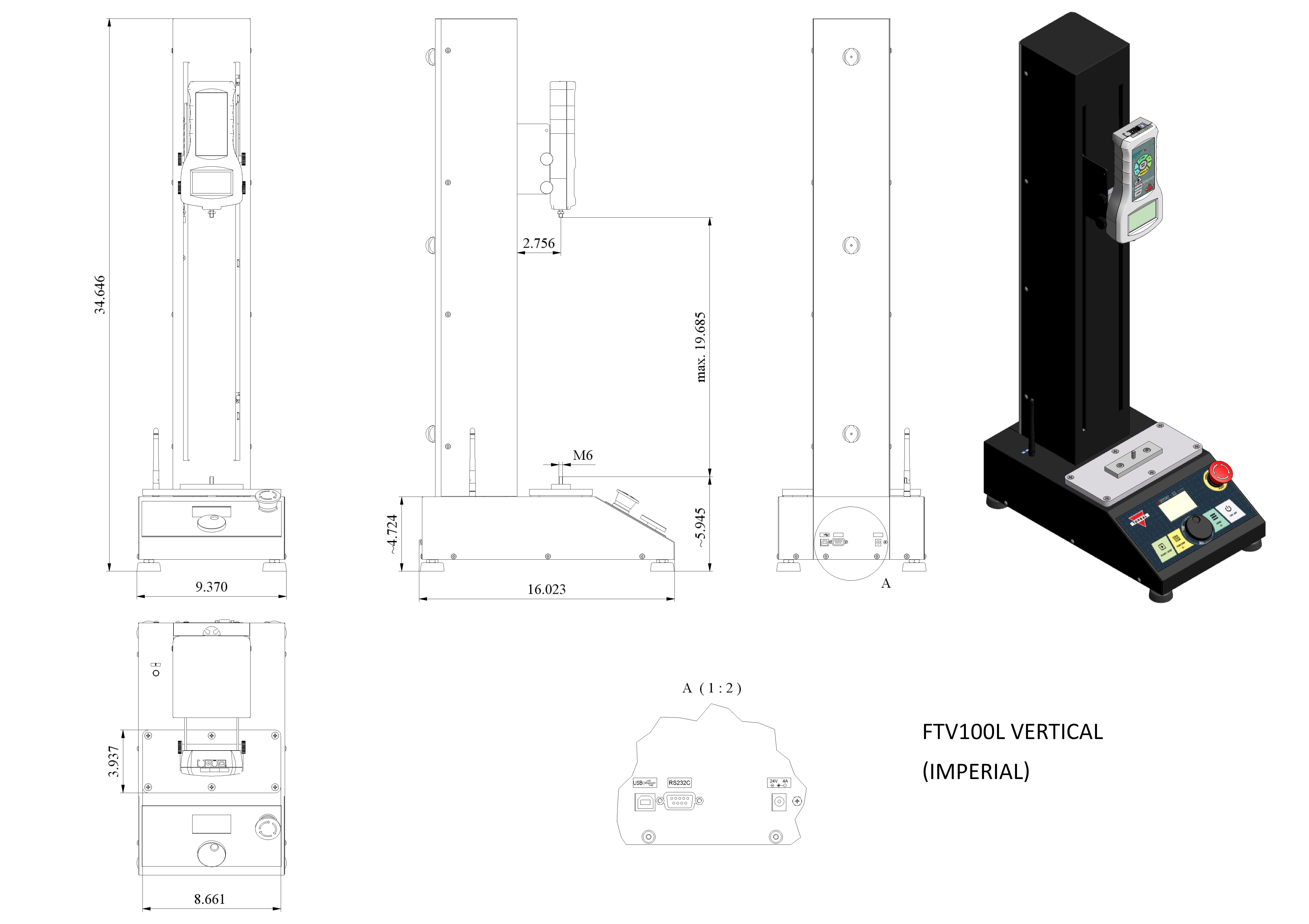
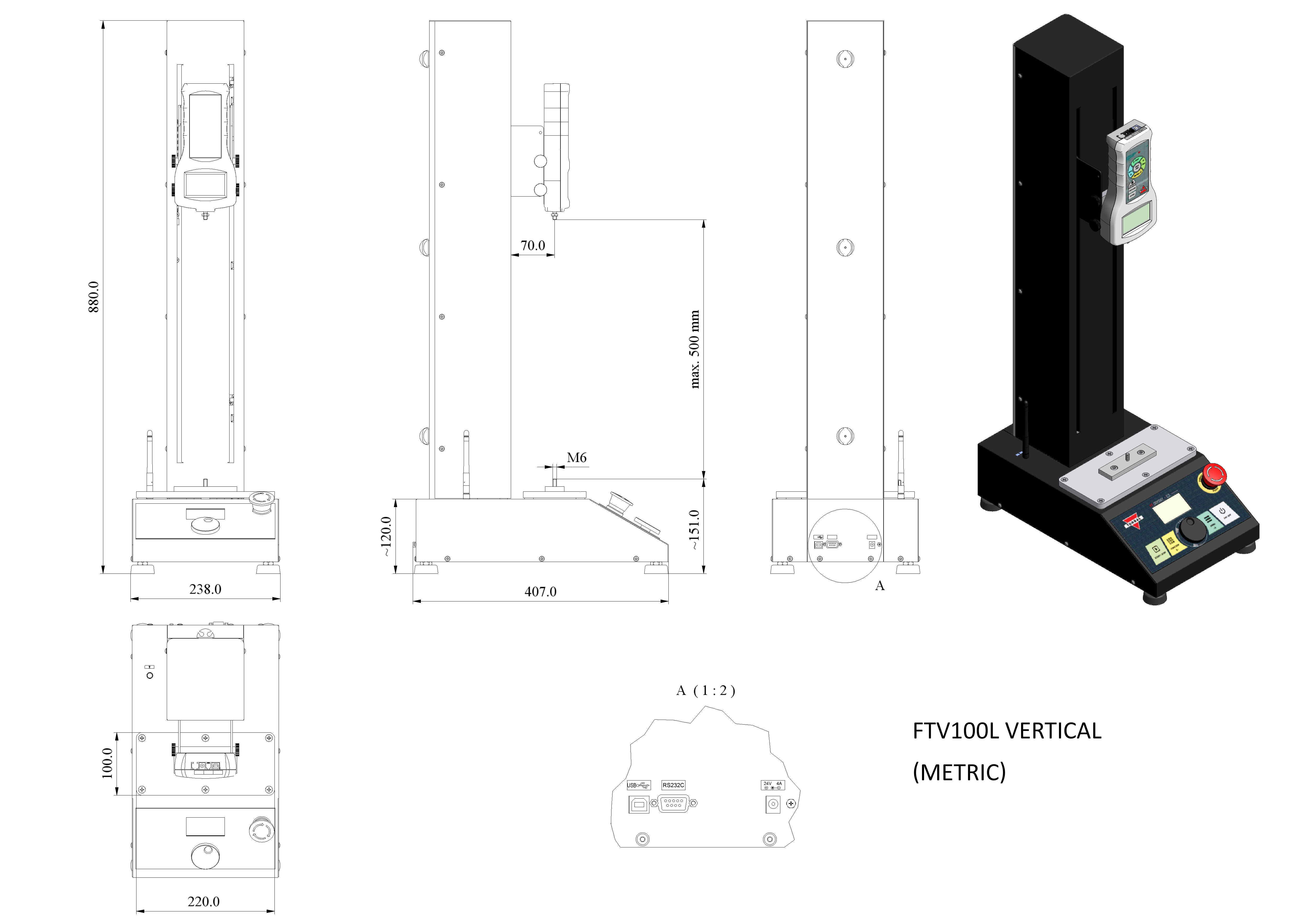
Vertical
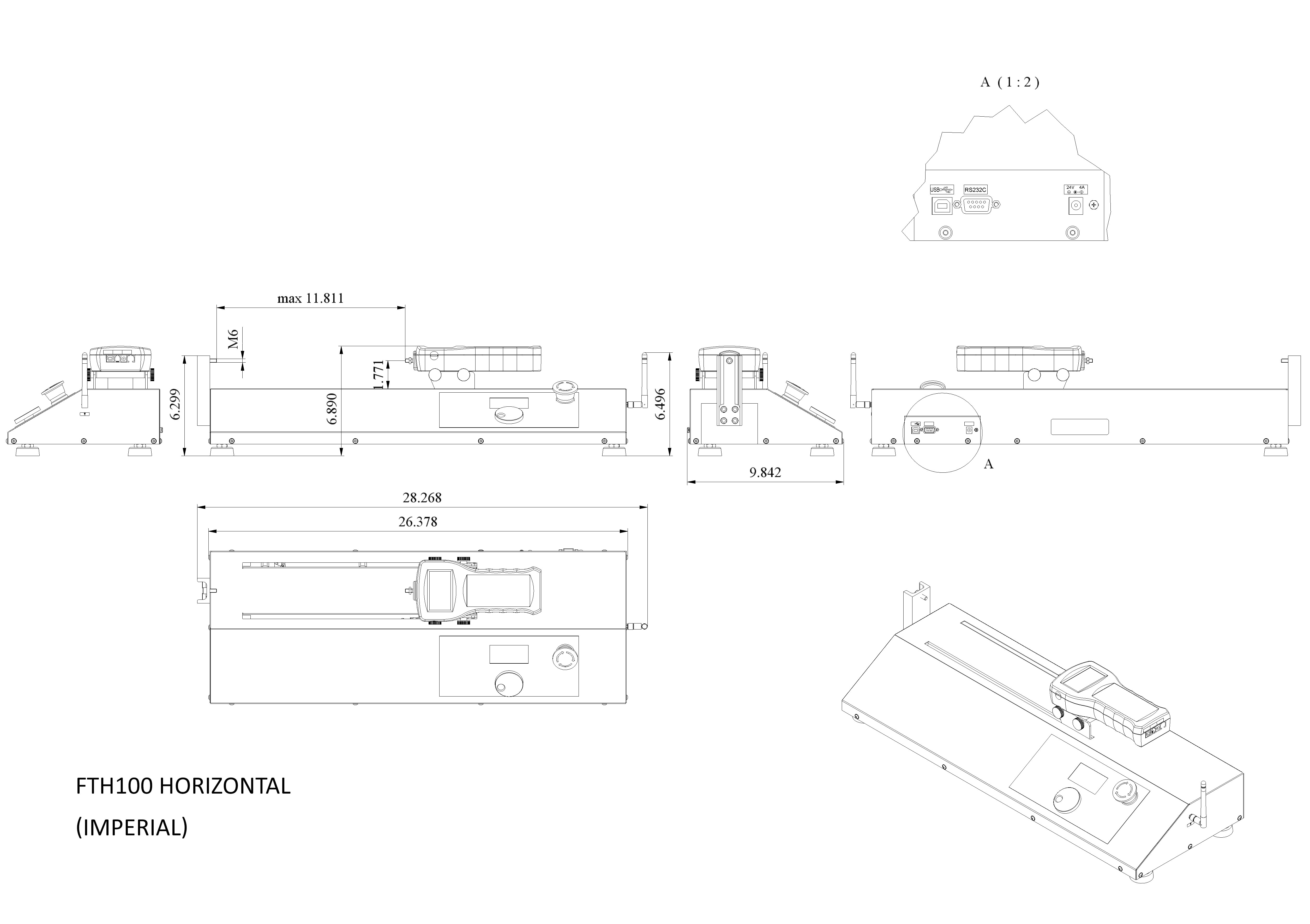
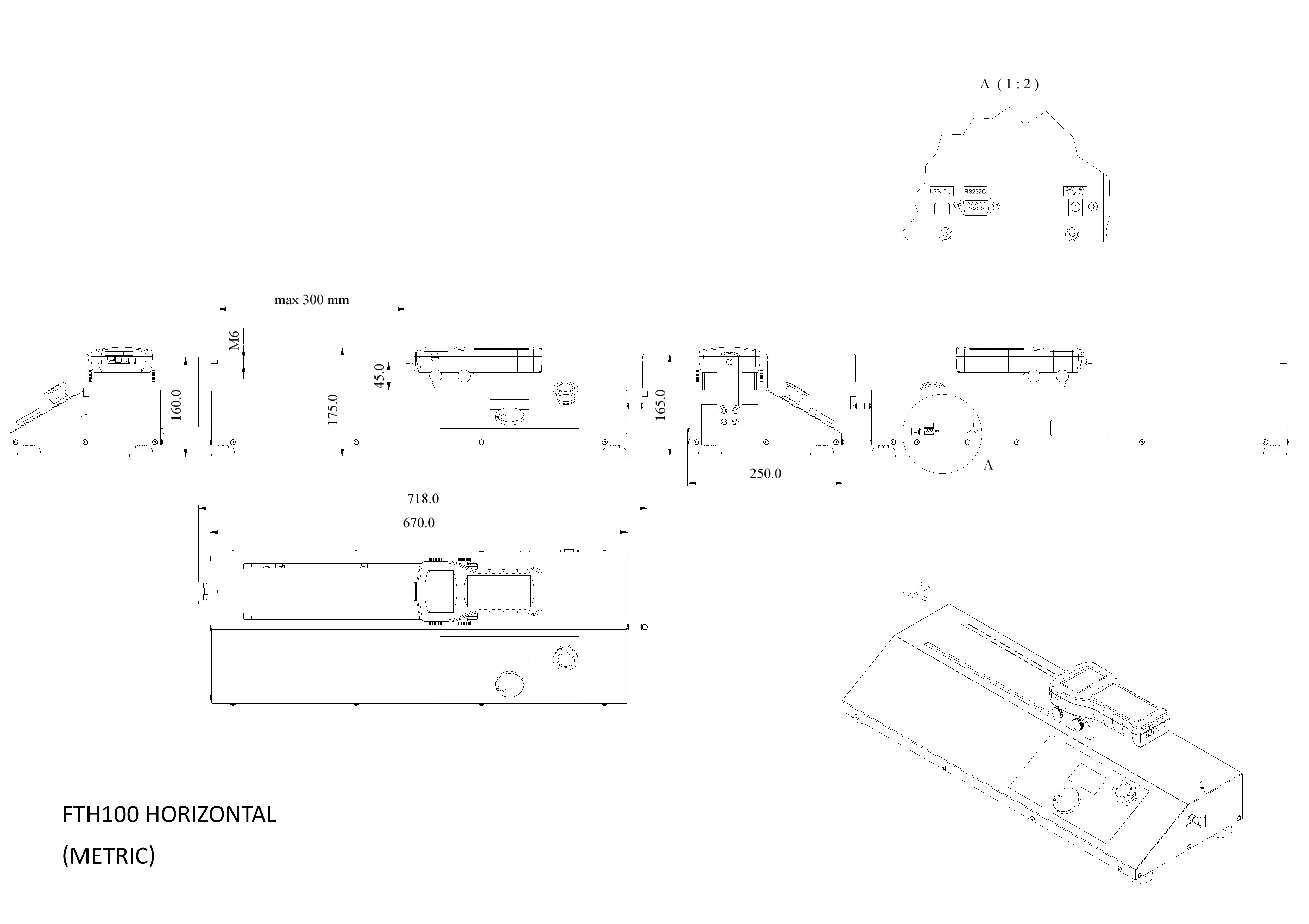
Horizontal
Test Stand Travel Distance and Max Load
Load: 112 lbF
Load: 112 lbF
Force Gauge Sampling Speed and Connection Type
Connection to test stand: Cable
Connection to test stand: Wireless
Force Gauge Capacity and Resolution
Features
Wireless Connectivity
No tangled or loose cables. The TORBAL Odyssey is equipped with a built-in wireless data transmitter which allows for cable-free connection between the test stand and the force gauge. Data can also be sent wirelessly to a windows PC or laptop.
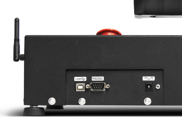
USB
Easily connect to a computer via USB which is standard on all Odyssey Test Stands. For users with a programming background, our advanced communication protocol enables full control of the test stand from a PC or laptop.
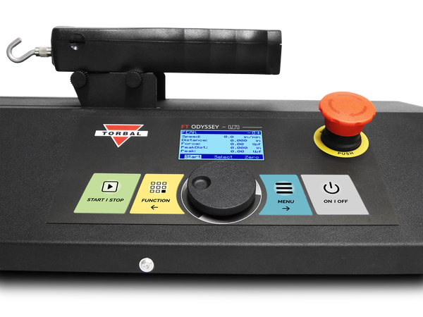
Intuitive Dial Knob Control
The quick wheel knob allows to manually move the test stand cross-head with a precision of 0.001in. Using the knob to move the cross-head to a starting and end positions is precise and trouble-free. The knob, combined with intuitively arranged keys, allows to quickly and effortlessly navigate through menus, scroll through options, and input data parameters.
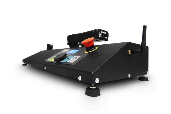
Premium Design
Purpose-built rugged design makes the ODYSSEY Test Stand ideal for the most demanding applications. A reinforced column, combined with an ultra-high-performance motor, and a heavy duty cross-head, guarantees uninterrupted performance and continuous testing. A versatile mounting plate with ample clearance and depth allows for ultimate flexibility in mounting a wide variety of samples.
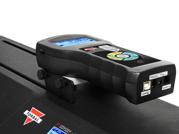
Easy Force Gauge Mounting
The test stand is supplied with mounting grip knobs that allow to easily mount the force gauge on the test stand and quickly adjust its position. Attaching and removing the force gauge is done effortlessly without the need for tools.
Functions
Accurate Speed Control
With a speed range of 0.4in/min to 11.in/min and accuracy of +/- 1% the ODYSSEY assures dependable performance at all times. Speed resolution of 0.1in/min guarantees surgical precision and allows for testing even the most delicate samples.
Precise Distance Travel
A travel distance ranging from 11.8in to 19.6in, travel accuracy as high as 0.004in, and resolution of 0.001in, allows you to set up the start and finish of the test with pinpoint precision, thereby guaranteeing repeatability and accuracy.
Intuitive Testing
Setting up a test is simple. All test stand modes are fully programmable through an intuitive user interface. Quickly configure test parameters and save them as a profile for future use. Store up to 50 profiles in each application mode. With over 15 configurable parameters, the Odyssey offers utmost programming flexibility to suit virtually any testing application.
Force Gauge Auto-Connect
The ODYSEEY’S auto detect ensures a painless-free out-of-the-box setup. The test stand automatically searches for connected force gauges at start up and instantly pairs.
Force Gauge Overload Protection
The overload protection feature provides stress free testing. The test stand continuously monitors loads applied to the force gauge to prevent overloads and damages.
Synchronized Force Gauge Control
All TORBAL force gauges seamlessly integrate with the test stand which enables control the force gauge through the test stand’s interface. The test stand automatically engages the force gauges time tests with a push of the start key.
PIN Protection
Pin protection secures critical testing parameters stored in application profiles with a unique six-digit numeric password. The feature safeguards against unauthorized access and usage.
Modes & Applications
Peak
The Peak application is used to measure peak force of a sample while controlling speed and distance of the cross-head. Test stops when the installed force gauge detects a peak. The test stand records the detected peak and distance at which the peak occurred.
| Programable Parameter | Description |
| Profile ID: | Profile name or number (9 characters) |
| Ref. Pos. Set. - Reference Position Set | Sets the starting position of the cross-head by moving the cross-head manual to the desired position with the dial-knob. Press on the dial-knob to put the cross-head in motion. |
| Ref. Pos. - Reference Position | Starting position of the test. Once a test profile has been selected the test automatically travels to the reference point. (in, mm) |
| Speed | Moving speed of the cross-head (in/min, mm/min) |
| Direction | Starting direction of the cross-head from the reference position. (Down / Up) |
| Load Stop | Test stops when a set load value is reached. (Off, Set lbF) |
| Distance | The distance required for the cross-head to travel. Cross-head will stop if traveled distance is reached before a peak occurs. (Off, Set “in” “mm”) |
| Auto Return | Cross-head automatically returns to the reference point after a peak has been detected or the test has been completed. |
Cycle
The Cycle application includes two modes: Cycle and Time. The test stand will repeat the programed cycle over a set number of cycles (Cycle mode), or over a preset time duration (Time mode). Up and Down travel speed of the cross-head may be set differently. The test stand displays Cycle No, Time remaining, Cross-head Speed, Travel, Force, and Hold Time.
| Programable Parameter | Description |
| Profile ID: | Profile name or number (9 characters) |
| Mode: <Cycles> <Time> | Cycle: test will run for the specified numbers of cycles. Time: test will run for a specified amount of time. |
| Cycles / Time | Number of Cycles or Time required. |
| Reference Position Set. | Sets the starting position of the cross-head by moving the cross-head manual to the desired position with the dial-knob. Press on the dial-knob to put the cross-head in motion. |
| Reference Position | Starting position of the test. Once a test profile has been selected the test automatically travels to the reference point. (in, mm) |
| D. Speed – Down Speed | Moving speed of the cross-head in the “Down” Direction (in/min, mm/min) |
| U. Speed – Up Speed | Moving speed of the cross-head in the “UP” Direction (in/min, mm/min) |
| Direction | Starting direction of the cross-head from the reference position. (Down / Up) |
| Distance | The distance required for the cross-head to travel. (Off, Set “in” “mm”) |
| Hold Time Ref. – Hold Time at Reference. | The amount of time the cross-head pauses at the reference point. |
| Hold Time End | The amount of time the cross-head pauses after traveling the distance amount. |
| Load Stop | Test stops when a set load value is reached. (Off, Set lbF) |
| Auto Return | Cross-head automatically returns to the reference point after a peak has been detected or the test has been completed. |
| Break Stop | When enabled the cross-head stops if a sample break is detected. The test stand performs its own break (peak) calculation from the measurements it receives from the force gauge. |
Step
Test is performed in steps. Each test can consist of maximum 12 steps. The sequence of steps can be set to cycle (repeat). Each step can differ in travel distance, speed, and hold time. The test stand displays the Step No., Speed, Travel, Force, and Hold Time (Countdown).
| Programable Parameter | Description |
| Profile ID: | Profile name or number (9 characters) |
| Steps: | Number of steps in the test. Parameter can differ for each step. |
| Ref. Pos. Set. - Reference Position Set | Sets the starting position of the cross-head by moving the cross-head manual to the desired position with the dial-knob. Press on the dial-knob to put the cross-head in motion. |
| Ref. Pos. - Reference Position | Starting position of the test. Once a test profile has been selected the test automatically travels to the reference point. (in, mm) |
| Cycles | All steps of the test will run for the specified numbers of cycles. |
| Auto Return | Cross-head automatically returns to the reference point after a peak has been detected or the test has been completed. |
| Break Stop | When enabled the cross-head stops if a sample break is detected. The test stand performs its own break (peak) calculation from the measurements it receives from the force gauge. |
| Step Parameters | |
| Direction | Starting direction of the cross-head from the reference position. (Down / Up) |
| Speed | Moving speed of the cross-head (in/min, mm/min) |
| Distance | The distance required for the cross-head to travel. (Off, Set “in” “mm”) |
| Hold Time | The amount of time the cross-head pauses after completing a step. |
| Load Stop | Test stops when a set load value is reached. (Off, Set lbF) |
Advanced
The advanced mode offers maximum programing flexibility. The mode compiles all programable parameters of the test stands allowing to create complex testing profiles with conditions that may not be achieved in standard application modes.
|
Programable Parameter |
Description |
||
|
Profile ID: |
Profile name or number (9 characters) |
||
|
Steps: |
Number of steps in the test. Parameter can differ for each step. |
||
|
Ref. Pos. Set. - Reference Position Set |
Sets the starting position of the cross-head by moving the cross-head manual to the desired position with the dial-knob. Press on the dial-knob to put the cross-head in motion. |
||
|
Ref. Pos. - Reference Position |
Starting position of the test. Once a test profile has been selected the test automatically travels to the reference point. (in, mm) |
||
|
Cycles |
All steps of the test will run for the specified numbers of cycles. |
||
|
Auto Return |
Cross-head automatically returns to the reference point after a peak has been detected or the test has been completed. |
||
|
Break Stop |
When enabled the test stand stops if a sample break is detected. The test stand performs its own break (peak) calculation from the measurements it receives from the force gauge. |
||
|
Step Parameters |
|||
|
Action |
Move Up |
Starting direction of the cross-head from the reference position. |
|
|
Move Down |
|||
|
Hold |
Time: The amount of time the cross-head paused. |
||
|
Constant Force |
The cross-head maintains specified constant force. The cross head performs minimum movements required to maintain a constant force applied within a specified tolerance range for a specified amount of time. |
Duration: The amount of time required to maintain the specified constant force. |
|
|
Force: The amount of force which will be maintained for a specified time. |
|||
|
Tolerance: Force tolerance specified in percent +/- used to maintain the position of the cross-head in order to maintain the specifies force. |
|||
|
Speed |
Moving speed of the cross-head (in/min, mm/min) |
||
|
End |
Travel |
Distance: The distance required for the cross-head to travel. |
|
|
Time |
Duration: Step will run for a specified amount of time. |
||
|
Sample Break |
Step stops if a sample break is detected. The test stand performs its own break (peak) calculation from the measurements it receives from the force gauge. |
||
|
Force |
Step ends when a set force conditions is met. |
Condition: Greater than or less than condition for the force value at which the step will end. |
|
|
Force: Specified force condition value |
|||
|
Position |
Step ends when cross-head reached the set position. |
||
Manual
The manual mode allows to control the test stand cross-head movement with the dial knob. Turning the dial to the left moves the cross head-up. Turning the dial to the right moves the cross-head down. The cross head can be set to move continually in a desired direction.
In the Box
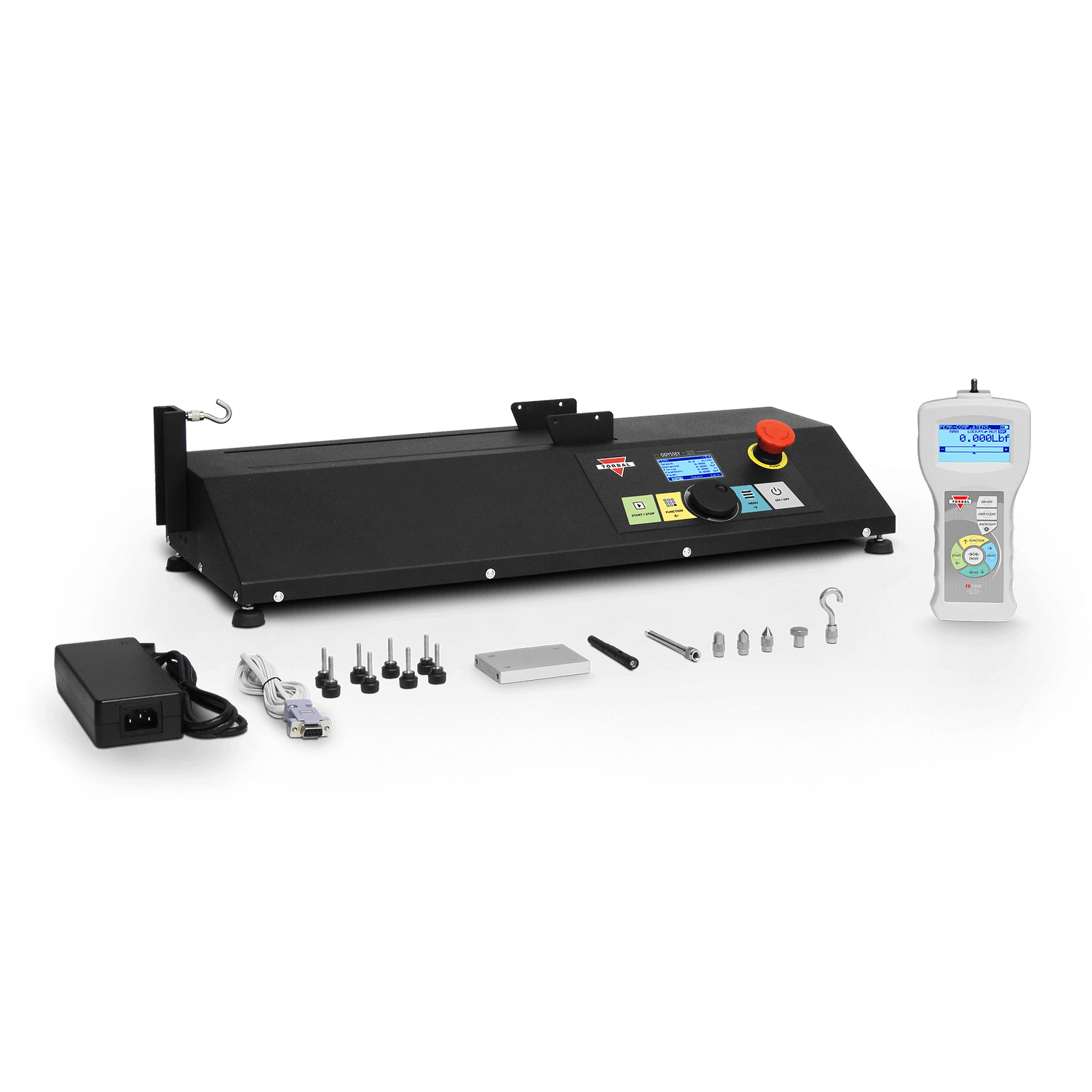
Test Stand
Horizontal 11” Travel with 112lbF Max Load Capacity
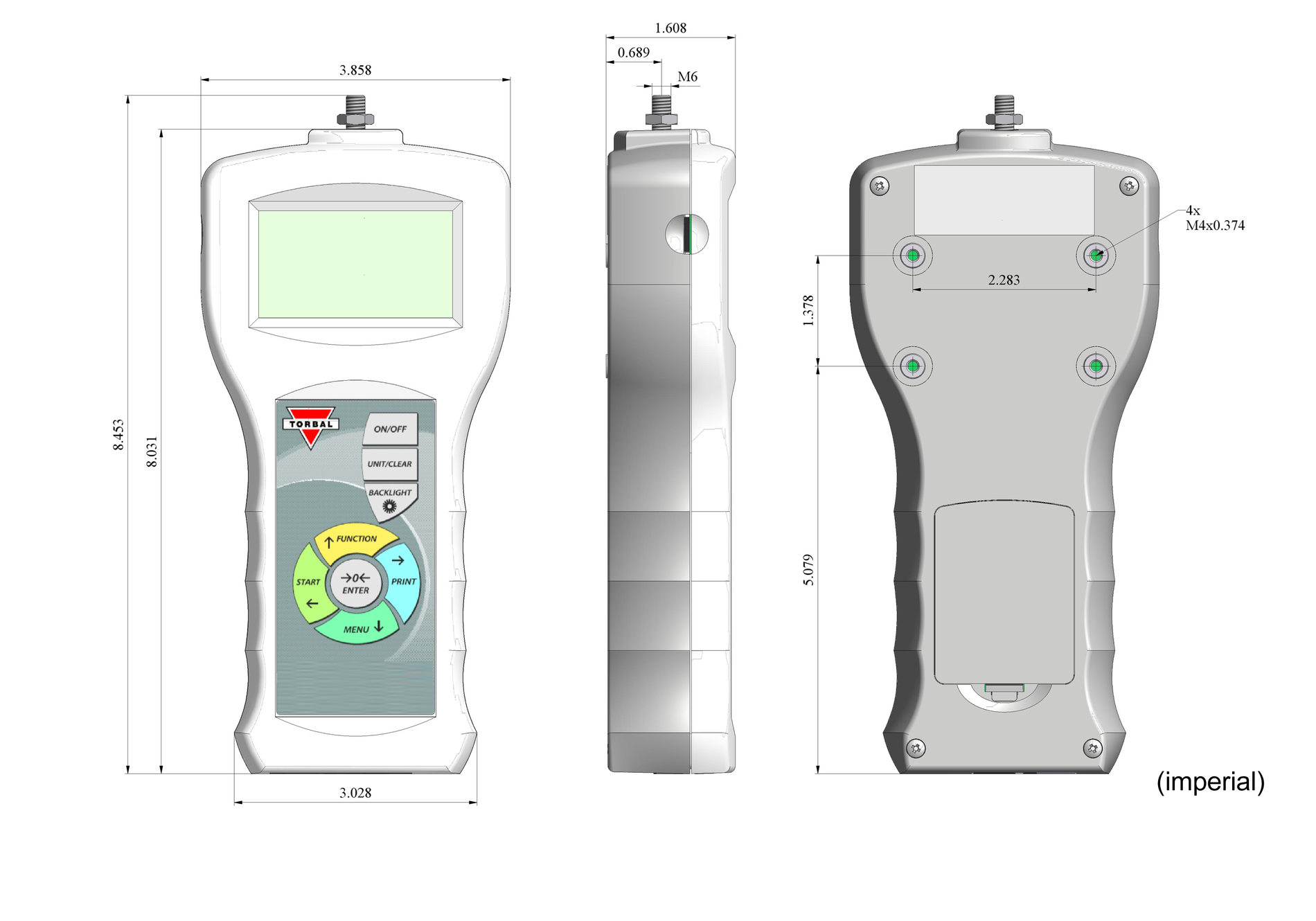
Force Gauge
4lbF x 0.001lbF
Speed: 80 Hz
Connection to test stand: Cable
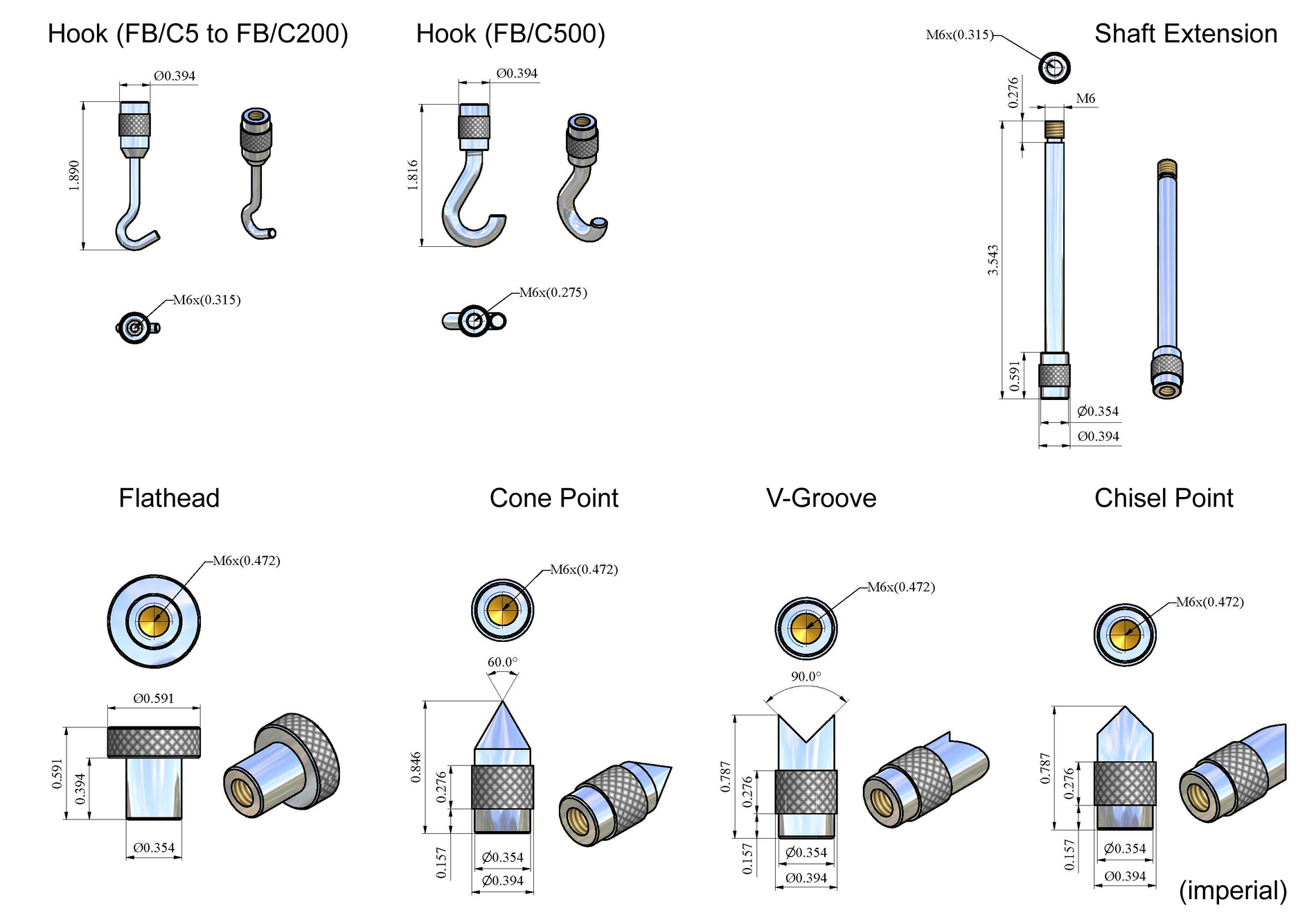
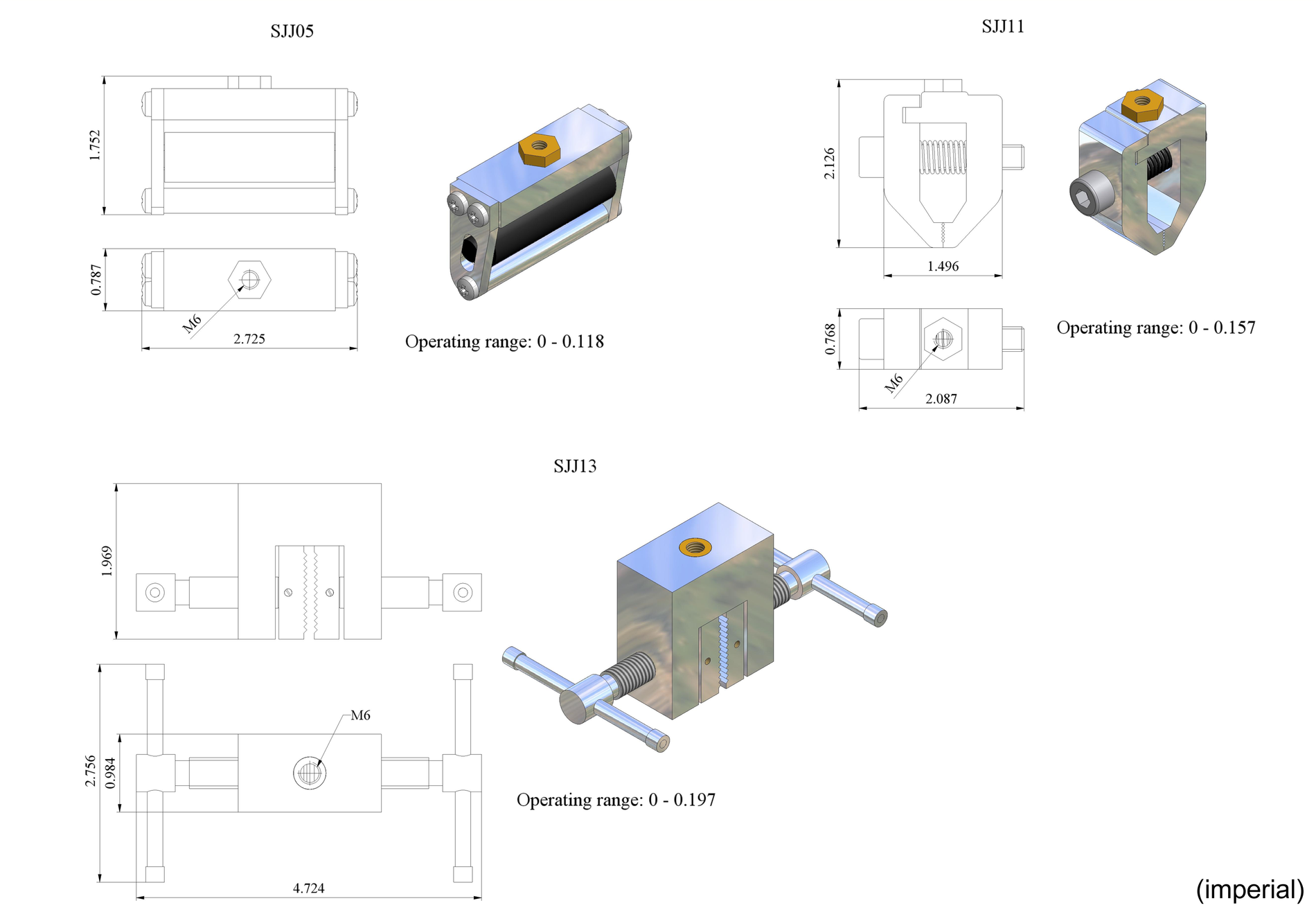
Complete set of tips and attachments
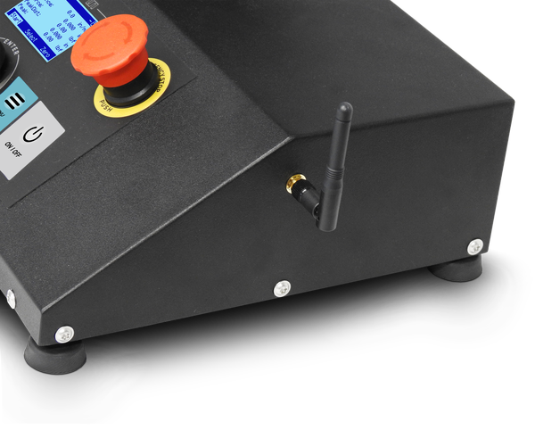
Antenna
High performance wireless antenna for cable free connection force gauge or PC
Mounting Plate
Force gauge mounting plate
Mounting Grip Knobs
Utility grip knob with galvanized threads for quick force gauge mounting
Connection Cable
RJ11 to DB9 flex cable for connection between force gauge and the test stand.
Power Adapter
24V, 100 – 240 VAC Switching power adaptor
Specifications
| Models | FTV – 100L | FTV – 100 | FTH – 100 |
| Load Capacity | 112lbf | 500N | ||
| Speed | 0.4 in/min – 11.8 in/min | 10mm/min - 300mm/min | ||
| Travel Distance | 19.6in | 500mm | 11.8in | 300mm | |
| Distance: Force Gauge Shaft to Column |
2.75in | 70mm | 1.77 in| 45mm | |
| Speed Accuracy | +/- 1% | ||
| Travel Accuracy | +/- 0.008 in | +/- 0.2mm | ||
| Speed Resolution | 0.1 in/min | 1 mm/min | ||
| Travel Resolution | 0.001 in | 0.01mm () | ||
| Rigidity * | 0.07 in | 1.8mm | 0.05 in | 1.4mm | 0.028 in | 0.7mm |
| Memory Profiles | 50 / application | ||
| Interface | BT Wireless, USB (B Type), RS232 | ||
| Measuring Units | in/min, mm/min | ||
| Operating Temperature |
50F – 104F | 10C – 40C | ||
| Power | 100-240VAC 50/60Hz 120W / 24VDC 4A | ||
| Dimensions | 238mm x 407mm x 880mm | 9.37in x 15.95in x 26.77in | 238mm x 405mm x 680mm | 28.27in x 9.84 x 6.50in | 718mm x 250mm x 165mm |
| Weight | 55.5lbs | 25kg | 50lbs | 22.5kg | |
| Box Weight | 99.5lbs | 45kg | 84lbs | 39kg | |
* Rigidity - Difference between distance from test stand mounting plate shaft to force gauge shaft under full load and no load